


The Carolina Hurricanes avoided another Eastern Conference Final sweep. In the West, Dallas is down 2-1 but hasn’t looked all that great in a series against...


The Florida Panthers are absolutely throttling the Carolina Hurricanes. In the Western Conference, the Edmonton Oilers look like the better team. Are we headed to a...


The Florida Panthers are seemingly getting better each game. The Dallas Stars are thriving on third-period comebacks. Also, Nathan MacKinnon suffered another third-period collapse and early...


The Florida Panthers are inching closer to yet another Stanley Cup Final appearance. Meanwhile, the hockey world awaits July 1 to see what happens with Mitch...


The Eastern Conference Final is underway tonight and starts 14 consecutive days of scheduled hockey. Also, an update on Nathan MacKinnon’s recent loss at the IIHF...


The Dallas Stars won Game 6 in overtime to advance to the Western Conference Final for the third consecutive year. Tonight, the Maple Leafs have a...


The Dallas Stars won Game 6 in overtime to advance to the Western Conference Final for the third consecutive year. Tonight, the Maple Leafs have a...


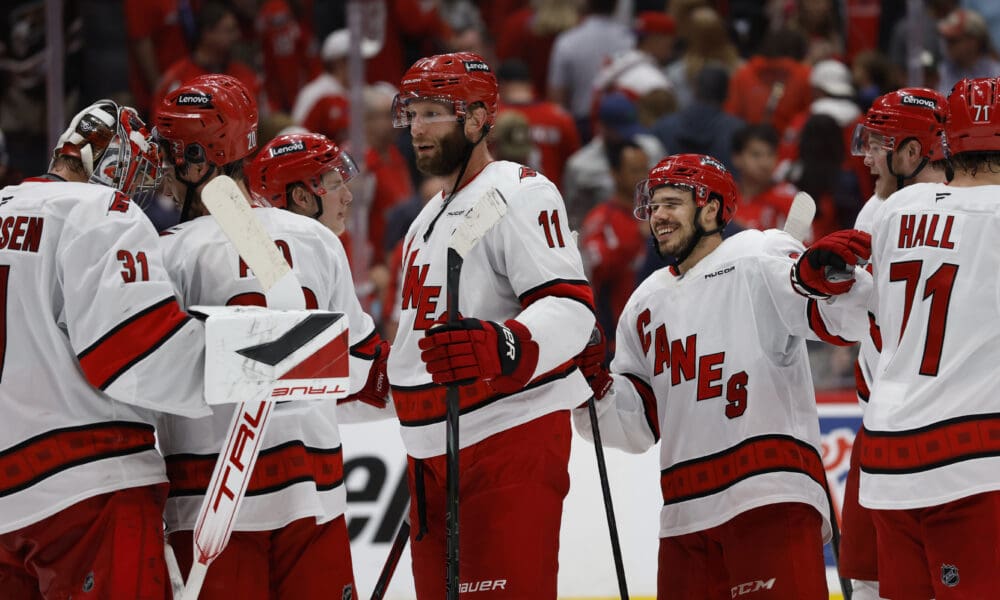
The Carolina Hurricanes are moving on. The Washington Capitals are going home. The Winnipeg Jets live to fight another day. Also, should the Avs bring...


One of the greatest Avs of all time has landed a head coaching job. In Toronto, the Maple Leafs were booed out of the building and...


What should the Avalanche do with pending unrestricted free agent Jonathan Drouin? Mikael Granlund had a hat trick to put Winnipeg on the brink of elimination....