


The Avs were listed as a potential destination to acquire one of their old fan favorites by a Sportsnet writer. Also, a retirement was announced, the...


Free agency starts tomorrow and pretty much all the names at the top of the board have been taken off. The Avs have holes to fill,...
The first segment of the post-playoff mailbag is here. What went wrong in the postseason for Colorado? Also, the Toronto Maple Leafs are looking pretty, pretty...


The captain was at practice on Monday and stuck around the whole way through. Can the Avalanche rely on both of their goalies in the playoffs?...


The Avs did it again. Nathan MacKinnon reached a milestone in the third period in Erik Johnson’s first game back. Also, Aaron Ekblad gets hit with...


Happy Halloween! With some nice weather in the forecast. I plan to go trick or treating tonight with my little guy. Yours truly will be going...

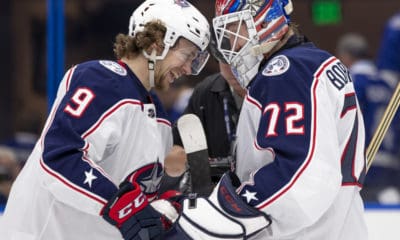

Last night was an exciting night for the family and Me. My son got to go to his first NHL game. I went to the Columbus...
